Overview
Schematics are our map to designing, building, and troubleshooting circuits. Understanding how to read and follow schematics is an important skill for any electronics engineer.
This tutorial should turn you into a fully literate schematic reader! We’ll go over all of the fundamental schematic symbols:

Then we’ll talk about how those symbols are connected on schematics to create a model of a circuit. We’ll also go over a few tips and tricks to watch out for.
Suggested Reading
Schematic comprehension is a pretty basic electronics skill, but there are a few things you should know before you read this tutorial. Check out these tutorials, if they sound like gaps in your growing brain:
Schematic Symbols (Part 1)
Are you ready for a barrage of circuit components? Here are some of the standardized, basic schematic symbols for various components.
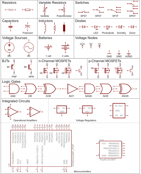
Resistors
The most fundamental of circuit components and symbols! Resistors on a schematic are usually represented by a few zig-zag lines, with two terminals extending outward. Schematics using international symbols may instead use a featureless rectangle, instead of the squiggles.
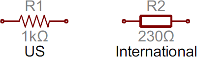
Potentiometers and Variable Resistors
Variable resistors and potentiometers each augment the standard resistor symbol with an arrow. The variable resistor remains a two-terminal device, so the arrow is just laid diagonally across the middle. A potentiometer is a three-terminal device, so the arrow becomes the third terminal (the wiper).
Capacitors
There are two commonly used capacitor symbols. One symbol represents a polarized (usually electrolytic or tantalum) capacitor, and the other is for non-polarized caps. In each case there are two terminals, running perpendicularly into plates.
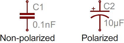
The symbol with one curved plate indicates that the capacitor is polarized. The curved plate represents the cathode of the capacitor, which should be at a lower voltage than the positive, anode pin. A plus sign might also be added to the positive pin of the polarized capacitor symbol.
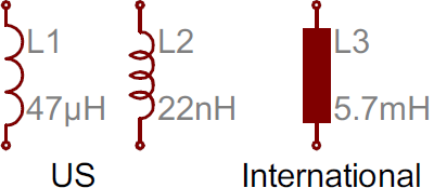
Inductors
Inductors are usually represented by either a series of curved bumps, or loopy coils. International symbols may just define an inductor as a filled-in rectangle.
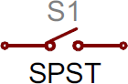
Switches
Switches exist in many different forms. The most basic switch, a single-pole/single-throw (SPST), is two terminals with a half-connected line representing the actuator (the part that connects the terminals together).
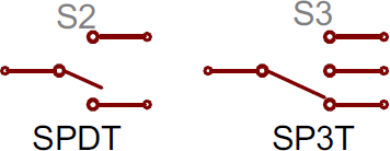
Switches with more than one throw, like the SPDT and SP3T below, add more landing spots for the the actuator.
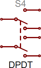
Switches with multiple poles, usually have multiple, alike switches with a dotted line intersecting the middle actuator.
Power Sources
Just as there are many options out there for powering your project, there are a wide variety of power source circuit symbols to help specify the power source.
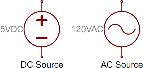
DC or AC Voltage Sources
Most of the time when working with electronics, you’ll be using constant voltage sources. We can use either of these two symbols to define whether the source is supplying direct current (DC) or alternating current (AC):
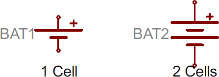
Batteries
Batteries, whether they’re those cylindrical, alkaline AA’s or rechargeable lithium-polymers, usually look like a pair of disproportionate, parallel lines:
*I'll stop right here. This site has every detail of what you'll need to know about reading schematics, I give it 5 stars and find it bookmark worthy.